Prosoft Datalogger w/ DF1 Comms to SLC 5/05 - Testing with MicroLogix

ISE

Supporting Member
Join Date
Apr 2024
Location
Indiana
Posts
2
I am working on setting up a Prosoft Datalogger model PLX51-DLplus-232. This unit will be collecting data from a SLC 5/05 on the DB9 port set to DF1. For testing i am utilizing a Micro 1100 since my spare SLC 5/04 doesn't want to let me download a fresh project to it for testing. In defense of the SLC it hasn't been plugged in for a couple of years and keeps giving me a comm fault mid download.

Now i realize a MicroLogix is not a SLC but it is my understanding that they act the same when it comes addressing and pulling data.

I have not been able to get the DF1 to communicate between the two modules. I am currently running a 1761-CBL-PM02/C from the Micro to a DB9 breakout board. On the breakout board i have jumpered pins 1,4,6 and 7,8 as per the drawing below:

1712777392330.png

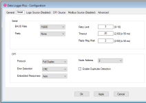
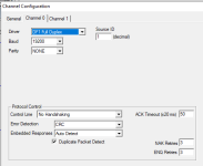
I currently have the communications setup as follows:
1712777580733.png

1712777630873.png

1712777684300.png

Anyone have any ideas on what i must be missing?

Thank you!
 
It should work without the jumpers. I am suspicious of your jumper to pin 1 (DCD). Most times with DF1 to a Micrologix when I need to fab a cable, I just use the 3 wires for RX, TX and signal ground. If it doesn't work and I am sure of my setup, I swap RX and TX just in case I misread the documentation for the 3rd party device. If you have a Micrologix 1400, it has a nine pin serial port that is even more similar to the SLC and should be electrically identical.
 
I don't know why I didn't try swapping the Tx / Rx, but you would think after this many years of doing this I would have.

Thank you....
 
If I was going to tweak any settings, I would set up the Datalogger's DF1 Node Address to 0 instead of 2.

DF1 Full Duplex point-to-point settings generally actually ignore the SRC and DST bytes, but devices that do examine them usually expect to treat the PLC as Node 1, and the polling client as Node 0.

Because the PM02 cable is meant to plug into a DTE type serial port, its Pin 2 should be connected to the Receive terminal of the Prosoft device. That is opposite to how you show on your diagram.

And I agree that I would pare it down to just Pins 2, 3, and 5.

The MicroLogix 1100 has both an RS-232 and an RS-485 port in its round connector, but no +24V power supply pin like the MicroLogix 1000, 1200, and 1500 did.
 

Similar Topics

Hi, We have an application that has a device that goes through a reboot (appears un-graceful) What then happens is the MVI module appears to hang...
Replies
0
Views
75
Hello. I am trying to use a Prosoft AN-X4 to improve the communications for a new panelview plus 7. This is going from a SLC-500 through DH+ to a...
Replies
9
Views
293
Hi. I'm using a Modbus ProSoft where I basically map data to a big INT array. Example, where GX_I_63HPU is a REAL, MNETC.DATA.WriteData[200] an...
Replies
21
Views
437
Hi everyone, I’m trying to copy the configuration from one MVI69-MCM to another. I am having no luck establishing serial comms with the device...
Replies
0
Views
89
hello, I have a problem with my AN-X2-AB-DHRIO Prosoft module, I can't connect with the module because I lost a microSD card that has firmware and...
Replies
12
Views
390
Back
Top Bottom