Programming S-curve motion profiles

Not unsatisfactory at all, it is very helpful thank you. However from what i can understand this has a constant acceleration is that correct? How would i add smoothing to the acceleration curve as well?

Thank you for your help!!
MaxK calculated the linear acceleration rate for ramping up and then ramping down. He did not provide a good polynomial that will result in a good s-curve.
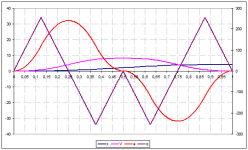
A s-curve should have an initial acceleration of zero and and final acceleration of zero at the end of the ramp up. Also the deceleration rate should be 0 at the beginning of the ramp down and and the ending of the ramp down. Since MaxK's constant acceleration rate is 16 m/s^2, the peak acceleration during the ramp up will be about 1.5 times that or 24 m/s^2. Are you sure you can accelerate that fast? That is over 2.3g. Also, MaxK calculated a peak speed of 8 m/s. Are the motor can move the load that fast? I haven't checked MaxK's calculations for acceleration but it looks reasonable. You should know whether the system will be speed or acceleration limited. There are tradeoffs that can be made where the top speed can be reduced if the motor can accelerate quicker.
The mass of your camera system will make a difference too.

After you have designed your system so it is possible to control then buy a real motion controller. Above, drbitboy posted some info about 7 segment motion. It is valid but it avoids the complexities on doing 7 segment motion control. I your case you can chose all the numbers so you don't have round off problems. For instance, what if a segment takes 66.66 millisecond to complete but your PLC can only do 1 millisecond scans. What do you do? A 33 millisecond error times 7 segments is a lot of time AND distance.
 
Almost 2 years have gone by since the start of this thread. Has anybody programmed a 7-segment motion profile on a PLC? No one has come up with the 17 formulas yet. I said early on that the S7-1500 has that function built in but so far no-one has claimed to have written a 7-segment motion profile in ladder or even ST. Why? 7-segment motion profiles are not easy, and it is cheaper to just buy the motion controller.

BTW, the old RMC100 used cosine ramps. I have posted how to do a simple 3rd order ramp on this forum before. In this case the position and velocity at the beginning and end are specified by the acceleration is not 0 and the beginning and end of the ramp.
 
Justforfun_2

A bit of Primary School math

x = x_0 + I x dt + II x dt^2 + III x dt^3 + IIII x dt^4 …

x = x_0 + V*t + a*t^2 / 2 + q * t^3 / 6 + f * t^4 / 24…


previous solution for 2-nd order
below solution for 3-rd order

x = x_0 + V*t + a*t^2 / 2 + q * t^3 / 6

Abs(q) – const
Symmetrical – “accelerations” “decelerations” equal each other
slidetime = 1 s

from previous
average a (0-0.5) = 16
so
a_0.25 = 16*2 = 32 m/s^2
t_0.25 = 1 / 4 s
q = a / t_0.25 = 32 / (1/4) = 32*4 = 128 m/s^3


t< 0.25

x = 128/6 * t^2

t> 0.25 and t< 0.75

x = x_0.25 + V_0.25*(t-0.25) + a_0.25*(t-0.25)^2 / 2 - q *(t-0.25)^3 / 6

x_0.25 = q*t_0.25^3 / 6 = 128 * (1/4)^3 / 6 = 128 / 64 / 6 = 1/3
V_0.25 = q*t_0.25^2 / 2 = 128 * (1/4)^2 / 2 = 128 / 16 / 2 = 4
a_0.25 = q*t_0.25 = 128 * (1/4) = 32

x = 1/3 + 4*(t-0.25) + 32*(t-0.25)^2 / 2 - 128 *(t-0.25)^3 / 6

t> 0.75

x = x_0.75 + V_0.75*(t-0.75) + a_0.75*(t-0.75)^2 / 2 - q *(t-0.75)^3 / 6

x_0.75 = x_0.25 + V_0.25*( t_0.75-t_0.25) + a_0.25 *( t_0.75-t_0.25)^2 / 2 - q*(t_0.75-t_0.25)^3 / 6 = 1/3 + 4*0.5 + 32*0.5^2/2 - 128 * (1/2)^3 / 6 = 1/3+ 2 + 4- 128 / 8 / 6 = 6 1/3 – 2 2/3 = 3 1/3
V_0.75 = V_0.25 + a_0.25 *( t_0.75-t_0.25) - q*(t_0.75-t_0.25)^2 / 2 = 4 + 32*0.5 - 128 * (1/2)^2 / 2 = 4 + 16- 128 / 4 / 2 = 4
a_0.75 = a_0.25 - q*( t_0.75-t_0.25) = 32 - 128 * (1/2) = - 32

x = 3 1/3 + 4*(t-0.75) - 32*(t-0.75)^2 / 2 + 128 *(t-0.75)^3 / 6


previous solution for 3-nd order
above solution for 4-rd order

x = x_0 + V*t + a*t^2 / 2 + q * t^3 / 6 + f * t^4 / 24

Abs(f) – const
Symmetrical – “accelerations” “decelerations” equal each other
slidetime = 1 s

from previous
average q (0-0.25) = 128
so
q_0.125 = 128*2 = 256 m/s^3
t_0.125 = 1 / 8 s
f = q / t_0.125 = 256 / (1/8) = 256*8 = 2048 m/s^4

boooooorrrrrriiiiing!!!!!!

See attached curves


yes, I know that this solution is unsatisfactory

and that’s why

Formally, Peter Nachtwey is right: if acceleration and deceleration are not symmetrical, if there are restrictions on speed, acceleration... if you need to recalculate curves “on fly”, then the task actually becomes quite difficult, and in this case it may actually make sense to buy a motion controller.

BUT!!! What exactly are your requirements and limitations?!!!
 

Attachments

  • 4s.png
    4s.png
    14.7 KB · Views: 8
Justforfun_2

A bit of Primary School math

x = x_0 + I x dt + II x dt^2 + III x dt^3 + IIII x dt^4 …

x = x_0 + V*t + a*t^2 / 2 + q * t^3 / 6 + f * t^4 / 24…


previous solution for 2-nd order
below solution for 3-rd order

x = x_0 + V*t + a*t^2 / 2 + q * t^3 / 6

Abs(q) – const
Symmetrical – “accelerations” “decelerations” equal each other
slidetime = 1 s

from previous
average a (0-0.5) = 16
so
a_0.25 = 16*2 = 32 m/s^2
t_0.25 = 1 / 4 s
q = a / t_0.25 = 32 / (1/4) = 32*4 = 128 m/s^3


t< 0.25

x = 128/6 * t^2

t> 0.25 and t< 0.75

x = x_0.25 + V_0.25*(t-0.25) + a_0.25*(t-0.25)^2 / 2 - q *(t-0.25)^3 / 6

x_0.25 = q*t_0.25^3 / 6 = 128 * (1/4)^3 / 6 = 128 / 64 / 6 = 1/3
V_0.25 = q*t_0.25^2 / 2 = 128 * (1/4)^2 / 2 = 128 / 16 / 2 = 4
a_0.25 = q*t_0.25 = 128 * (1/4) = 32

x = 1/3 + 4*(t-0.25) + 32*(t-0.25)^2 / 2 - 128 *(t-0.25)^3 / 6

t> 0.75

x = x_0.75 + V_0.75*(t-0.75) + a_0.75*(t-0.75)^2 / 2 - q *(t-0.75)^3 / 6

x_0.75 = x_0.25 + V_0.25*( t_0.75-t_0.25) + a_0.25 *( t_0.75-t_0.25)^2 / 2 - q*(t_0.75-t_0.25)^3 / 6 = 1/3 + 4*0.5 + 32*0.5^2/2 - 128 * (1/2)^3 / 6 = 1/3+ 2 + 4- 128 / 8 / 6 = 6 1/3 – 2 2/3 = 3 1/3
V_0.75 = V_0.25 + a_0.25 *( t_0.75-t_0.25) - q*(t_0.75-t_0.25)^2 / 2 = 4 + 32*0.5 - 128 * (1/2)^2 / 2 = 4 + 16- 128 / 4 / 2 = 4
a_0.75 = a_0.25 - q*( t_0.75-t_0.25) = 32 - 128 * (1/2) = - 32

x = 3 1/3 + 4*(t-0.75) - 32*(t-0.75)^2 / 2 + 128 *(t-0.75)^3 / 6


previous solution for 3-nd order
above solution for 4-rd order

x = x_0 + V*t + a*t^2 / 2 + q * t^3 / 6 + f * t^4 / 24

Abs(f) – const
Symmetrical – “accelerations” “decelerations” equal each other
slidetime = 1 s

from previous
average q (0-0.25) = 128
so
q_0.125 = 128*2 = 256 m/s^3
t_0.125 = 1 / 8 s
f = q / t_0.125 = 256 / (1/8) = 256*8 = 2048 m/s^4

boooooorrrrrriiiiing!!!!!!

See attached curves


and that’s why

Formally, Peter Nachtwey is right: if acceleration and deceleration are not symmetrical, if there are restrictions on speed, acceleration... if you need to recalculate curves “on fly”, then the task actually becomes quite difficult, and in this case it may actually make sense to buy a motion controller.

BUT!!! What exactly are your requirements and limitations?!!!
We can recompute the motion profile on-the-fly This has been necessary from the beginning since 1986,
Justforfun_2

A bit of Primary School math

x = x_0 + I x dt + II x dt^2 + III x dt^3 + IIII x dt^4 …

x = x_0 + V*t + a*t^2 / 2 + q * t^3 / 6 + f * t^4 / 24…


previous solution for 2-nd order
below solution for 3-rd order

x = x_0 + V*t + a*t^2 / 2 + q * t^3 / 6

Abs(q) – const
Symmetrical – “accelerations” “decelerations” equal each other
slidetime = 1 s

from previous
average a (0-0.5) = 16
so
a_0.25 = 16*2 = 32 m/s^2
t_0.25 = 1 / 4 s
q = a / t_0.25 = 32 / (1/4) = 32*4 = 128 m/s^3


t< 0.25

x = 128/6 * t^2

t> 0.25 and t< 0.75

x = x_0.25 + V_0.25*(t-0.25) + a_0.25*(t-0.25)^2 / 2 - q *(t-0.25)^3 / 6

x_0.25 = q*t_0.25^3 / 6 = 128 * (1/4)^3 / 6 = 128 / 64 / 6 = 1/3
V_0.25 = q*t_0.25^2 / 2 = 128 * (1/4)^2 / 2 = 128 / 16 / 2 = 4
a_0.25 = q*t_0.25 = 128 * (1/4) = 32

x = 1/3 + 4*(t-0.25) + 32*(t-0.25)^2 / 2 - 128 *(t-0.25)^3 / 6

t> 0.75

x = x_0.75 + V_0.75*(t-0.75) + a_0.75*(t-0.75)^2 / 2 - q *(t-0.75)^3 / 6

x_0.75 = x_0.25 + V_0.25*( t_0.75-t_0.25) + a_0.25 *( t_0.75-t_0.25)^2 / 2 - q*(t_0.75-t_0.25)^3 / 6 = 1/3 + 4*0.5 + 32*0.5^2/2 - 128 * (1/2)^3 / 6 = 1/3+ 2 + 4- 128 / 8 / 6 = 6 1/3 – 2 2/3 = 3 1/3
V_0.75 = V_0.25 + a_0.25 *( t_0.75-t_0.25) - q*(t_0.75-t_0.25)^2 / 2 = 4 + 32*0.5 - 128 * (1/2)^2 / 2 = 4 + 16- 128 / 4 / 2 = 4
a_0.75 = a_0.25 - q*( t_0.75-t_0.25) = 32 - 128 * (1/2) = - 32

x = 3 1/3 + 4*(t-0.75) - 32*(t-0.75)^2 / 2 + 128 *(t-0.75)^3 / 6


previous solution for 3-nd order
above solution for 4-rd order

x = x_0 + V*t + a*t^2 / 2 + q * t^3 / 6 + f * t^4 / 24

Abs(f) – const
Symmetrical – “accelerations” “decelerations” equal each other
slidetime = 1 s

from previous
average q (0-0.25) = 128
so
q_0.125 = 128*2 = 256 m/s^3
t_0.125 = 1 / 8 s
f = q / t_0.125 = 256 / (1/8) = 256*8 = 2048 m/s^4

boooooorrrrrriiiiing!!!!!!

See attached curves


and that’s why

Formally, Peter Nachtwey is right: if acceleration and deceleration are not symmetrical, if there are restrictions on speed, accelerThation... if you need to recalculate curves “on fly”, then the task actually becomes quite difficult, and in this case it may actually make sense to buy a motion controller.

BUT!!! What exactly are your requirements and limitations?!!!
You have a valid solution that will work only if the OP's system can accelerate that quickly. You are right about knowing about the system.
In the past I would sometimes get calls and a customer would tell me what he wants to do. How much mass, how far, how much time. I have Mathcad worksheets that can quickly do the calculations. Sometime a customer would want to do the impossible and I would tell him so. I would save the customer a lot of money but he had to ask the right questions before he started the design. Afterwards it is too late and too expensive to change.
 
I am waiting. The 7-segment profile isn't too hard if the move is long so the acceleration, velocity and speed limits are reached.
yeah. But it's the others, where the duration of some segments are zero (or negative), that are going to be interesting.

Are you talking about a 3rd order system with restrictions?
Let's forget about math.
It seems to me that there is one technical and commercial contradiction here:
For non-critical systems (in which there are not strict requirements for time and accuracy of reaching a given position), you can come up with some simplified solutions (for example, calculate the system parameters for “slowest” parameter and reduce the entire solution to an algorithm with 2 acceleration reversals as in #63).

If you need exact solutions then:
1. I am sure that PN has these solutions.
2. Even if someone publishes mathematics, it is extremely doubtful that any of the "askers" will code it
3. And the strangest thing: if exact control is really required, then motion controllers exist for these purposes - why does PN create competition for his colleagues?
 
I have had the solutions for over 20 years now since we started development on the RMC75. The older RMC100 used cosine ramps.
There truly are 17 equations and 17 unknowns to solve for.
When I got call about a project, I would ask if it was a new project and how much mass, how fast and in how much time the motion would take. I have Mathcad work sheets that would quickly give me an idea of what is required.
Just off the top of my head I had formulas for a motion profile that would accelerate for 1/3 the time, decelerate 1/3 the time and go at a constant velocity 1/3 of the time. The acceleration ramp and the deceleration ramp would be 1/4 of the total distance. This is a good compromise between acceleration and velocity

Code:
velocity=(3*Δx)/(2*Δt)
acceleration = (9*Δx)/(2*Δt^2)

However, this assumes linear ramps, not s ramps.
For the OP this means the average acceleration will be 18 m/s and the constant velocity will be 6 m/s. This is quite a bit less than what MaxK computed.
For s-ramps the peak acceleration will be about 1.5 times the average acceleration. Divide the acceleration time in thirds and the jerk times will be 1/9 of a second. This ramp and jerk times are not even numbers. So how do you do this if the PLC scan time is even as fine as 1 millisecond?

Below is a snap shot of my directory 7 segment work files. There are all sorts of combinations of segment combinations. The OP will only need the one seg1234567. I post this so you guys get an idea of the complexity of a good 7 segment motion generator. The PID control is nothing compared to this.
 

Attachments

  • segdir.png
    segdir.png
    44.5 KB · Views: 13
Last edited:
to #69

My knowledge covers everything from the moment of singularity (and even a little earlier); in fact, my knowledge is the Universe itself.
Wisdom incomprehensible to your mortal minds was given in 17 sacred tablets and 17 secret runes.

Behold the truth that has been revealed to me: a triangle has 3 angles!
But my wisdom extended further. Behold: a square is endowed with 4 corners!

Code:
WiseCode
Triangle – 1,2,3 angles
Square – 1,2,3,4 angles

However, the question was about a circle (or an ellipse??? or...) (who cares!!!)
4 – 3 = 1
4 / 3 = 1 1/3
As you can see, my calculations have nothing in common with the primitive calculations of MaxK (about a circle, or an ellipse... who cares!!!)

For a circle, blah blah blah will be about 1.5 times blah blah blah. Zuzuzuzyuzu will be 1/9 of a second. This radius and length are not even 84 (or 93, or at least 15). So how, you nonentities, will you do this if the abacus is 28 beads?

Below is a snap shot of my directory of My infinite wisdom files. Here are all sorts of wisdom:
secrets of all intelligence services in the world, a complete list of members of the Masonic conspiracy, the reptilian conspiracy, the answer to the question "Who Framed Roger Rabbit". But there is NO answer to the most important question: “What happened to PN’s self-criticism/egoless/unpretentious?”

The OP will only need the... who cares what he need!!!. I'm post this to make you guys aware of your insignificance and the absurdity of your attempts to communicate with PN. Anything is nothing compared to this (because no opinion, question or view that differs from the PN deserves absolutely no attention for the reasons stated above).
 
Bitter you are. Perhaps you would prefer to see my directory of recorded bugs I found along the way. I found and fixed many.

I pointed out that that what the OP wants to do might be very difficult because of the high speeds and accelerations. The motion profile doesn't matter if it can't be achieved. I have saved people a lot of money over the years by pointing this out. Some applications could be done but the machine would cost too much.

For what the customer wants to do, cosine ramps are easy. Much easier than 3 segment 3rd order ramps. The old RMC100 only had an 80186 with no floating point so using polynomials was out of the question. I mentioned this early on, but no one listened.
 
@MaxK....Not at all fair!

Some time ago, I did a search for s-curve and it brought me to Pete's super-simple routine that I implemented in interpreted BASIC on an RPi-Pico.
Trapezoidal wasn't as smooth as I wanted. Now I have a 1Khz PID and trajectory generator on a $10 MCU with a $5 quad-decoder/counter (LS7366) and a $5 12-bit DAC, running on a self-hosted, zero-cost-open-source, BASIC interpreter.....Beautifully :cool:

None of this ripoff PLC claptrap that nobody can work with once their license has expired.

Many thanks Pete. (y)

Edit: Forgot to mention the (ridiculous) 64bit position range and the (equally ridiculous) 40M quad-cts/sec
 
Last edited:
@Tinine, was that the ramp fraction version?
where
Code:
f =  t/ramp_time
When ramping up
x(f)=ramp_dist*(3*f^2-2*f^3)+x(0)
when ramping down
x(f)=x(1)-ramp_dist*(1-3*f^2+2*f^3)
f always goes between 0.0...1.0 so it is easy to do the calculations.
This works for positions and velocities.
Take the derivative to get velocity.

I have a fifth order version too. where the accelerations begin and end at 0 during the ramps.

However, it makes no difference if the motor can't move or accelerate fast enough.
The OP never got back to us on that.
 
Yup, that's the one and it works an absolute treat (y)

However, it makes no difference if the motor can't move or accelerate fast enough.
The OP never got back to us on that.

Yeah I know and the same thing applies with super-high rates of PID sampling. I find that lower (500Hz) are easier to tune, in some cases and I lose nothing.
 
@Peter Nachtwey

Oh wait, it's been a while but why does mine look simpler?

dim as integer res,samptime
dim as float f,intspeed,ramp_segments,frac

ramp_segments = 1/1000
res = 1000

sync 1,M 'this provides the 1ms determinism

do
inc samptime,1
sync
frac = samptime*ramp_segments

f=(3-2*frac)*frac^2

intspeed = f * 5000
print samptime, intspeed
loop until samptime=>res

This was my original test routine
 

Similar Topics

Hey everyone, I have a sensor that gives a 4 - 20 mA signal that is not perfectly linear. There is a bit of a curve in it. I would like to hook...
Replies
27
Views
4,830
Does anyone can explain me how to do s-curve (for increasing and decreasing speed of the process ) programming in siemens simatic S7. If...
Replies
1
Views
1,889
Hi, I am trying to set up a plc. I've never done any programming with ladder logic previously. I'm trying to set up a a program to turn a device...
Replies
6
Views
70
Dear all, I have fx2n plc on my hand but I don't have the programming cable sc-09 and it would not be easy for me to get one. I need the cable...
Replies
3
Views
117
Hi all, i am the new controls guy at the plant and i have inherited a pc from the previous controls guy with Siemens tia portal version 16 and 17...
Replies
20
Views
905
Back
Top Bottom