Mitsubishi Q series Analog Input Module Programming

Join Date
Sep 2017
Location
Gazaria,Munshiganj
Posts
30
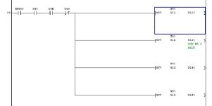
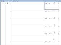
In this sample programming, what does U4 mean?

Any assistance would be greatly appreciated.
 

Attachments

  • 1.JPG
    1.JPG
    19.7 KB · Views: 32
  • 2.JPG
    2.JPG
    29.8 KB · Views: 35
  • 3.JPG
    3.JPG
    65.3 KB · Views: 31
  • 4.JPG
    4.JPG
    52.2 KB · Views: 36
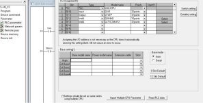
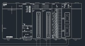
It means that good execution of your program is not possible with PLC on picture "4.jpg".
"U4" designates fifth intelligent module on the right side of PLC, but you have only two intelligent modules ("U0" and "U1").
 
Yes the U designation is the card number starting at 0 for the first slot in the rack, the G is the buffer memory for example U0/G12 would mean card zero buffer memory 12 (you need to look at the manual for the allocation of the buffer memories, Usually Buffer memories (BFM for the analogue channels are from 10 to what ever (depending on the number of channels there can be over a hundred BFM' for all sorts of control/information i.e. filters, diagnostics).
Certain BFM's require writing to others you read, there are other functions that do the same thing the TO/FROM functions can be used TO means write to the BFM memory the FROM is fetch data from the BFM, it also allows more than one location to be written or read from for example FROM 0, 10, 4, D100 means read BFM memory from card 0, BFM10 and 4 registers (BFM10,11,12,13) and store them in D100-D103.
 
Last edited:
It means that good execution of your program is not possible with PLC on picture "4.jpg".
"U4" designates fifth intelligent module on the right side of PLC, but you have only two intelligent modules ("U0" and "U1").
Thanks for your reply. So the designation of Q64AD should be U0 based on your opinion, Am I right?
 
No according to your configuration of the cards your QD64 is in slot 3 Designated as Address U2 so should be U2/Gxx.
I notice you are using X0 to enable the card, this is not normal as the values would either not read if X0 goes off & the value in the register would stay as per last enable, generally you either read every scan or on a timer so either use SM400 (On from first scan) SM401, and SM402 for initial scan to set the card up i.e. set the type of analog inputs etc.
Actually I mifght be slightly wrong it could be U3 not U2 I cannot remember now if it is the slot number not the X,Y address so I think you address it as slot number & you can access the I/O (not bFM's) like X2.0 or Y2.0.
 
I will check again, but as I remember you count only intelligent modules,.so it should be U0 I have one Q at my workshop, so I will check it later.
 
@goghie, now you have me wondering but I don't think so I cannot check at the moment as the only programs I have here at the moment are GXIEC & we used pre-configured FB's on Remote I/O for the analogues.
 
The last few years I have used GXConfigurator & set them to Auto refresh so no programming needed in the PLC scan program
 

Similar Topics

This is for a Q68DAIN 8-channel analog output. Most of the channels are outputting 0-20mA but a couple are outputting 10vDC Anyone know what rung...
Replies
11
Views
1,738
I am working with Fx2N-2DA and Fx0N-3A card ? what is the ladder logic for this two card ?
Replies
1
Views
1,980
Hello. I've been learning about PLC's in a few months now, mainly PLC programming, and yesterday I got an assignment to read an analog laser...
Replies
3
Views
4,605
Hello friends; I am new with Mitsubishi system. I need some example to handle the 4-20mA by using FX-2n-4AD which is attached with FX-1N-14M...
Replies
5
Views
3,557
how to communicate FactoryTalk Optix and Mitsubishi Q Series. I want to know the details of that
Replies
0
Views
37
Back
Top Bottom