[Part 1 of 2:]
What is the programming tool you are using here ?
It is the IDE for an Allen-Bradely software program called RSLogix Micro Starter Lite, and it is used to program MicroLogix PLCs, but I suspect is similar to the IDE you have for programming the Xinje, and most of the instructions demonstrated in that RSLogix IDE will have equivalents in the Xinje IDE.
I looks as if its very simple (though I still do not understand most of it, maybe because this is my very first PLC code for an industrial application) Xinje looks so complex.
Every set of tools looks complex when you start. The only way to learn is to look at each individual tool (instructions) and learn how it works and what it is capable of doing. For example, the
-| |- Normally Open Contact and the
-|↑|- Rising Edge Pulse instructions are similar in some ways but have different behaviours, dependent on the values of their input rungs and operands (the operand is the bit, e.g. M0 or T1, above the instruction).
Tbh I really don't understand yours and
@parky's concepts on 'integer', 'sequence' 'state', 'eval', 'no sphagetti', 'refactor', 'step', 'pattern', 'JSR'
The PLC program is a model of the process (the process is the cylinders, switches, sensors, etc.). Any PLC program maintains its model of the process by reading and examining the values from the PLC inputs, and controls the process by manipulating the PLC outputs (forward and reverse, extend and retract cylinders, send pulses to the motor, etc.). One common name for such a model in the PLC is "state machine."
Xinje calls integers "words" - you are loading integer values into word registers (D10, D11, D20) in the first rung of your main program.
"Sequence" means you want the process to perform several unique operations over time and in a certain order i.e. in a certain sequence. For example, based on
@parky's earlier post:
Code:
State 0 = Initial step or Reverse Pulses completed; IDLE
State 20 = Start pressed; wait for a Garment to be detected.
State 30 = Garment Detected; delay before holding garment
State 40 = Delay completed; extend cyclinders, and wait for cylinder sensor to indicate garment is held
State 50 = Garment held; move guide motor forward (send pulses) and cut material, wait for pulses to complete
State 60 = Forward Pulses completed; stop motor and cutting, delay before reversing and unclamping
State 70 = Delay completed; reverse guide mode and release garment (retract cylinders), wait for pulses to complete (return to 0)
"State" and "step" mean the same thing: the state of the PLC model during one of those sequenced unique operations. The division of the process into a sequence of unique operations (states) is somewhat arbitrary, but the important point and
constraint is that the can be in only one state at any given time. It is convenient to a designate an integer value (Xinje "word") as the "state" or "step" of each unique operation (see state numbers above), and to put one of those values into a "STATE" or "STEP" register e.g. D200. Since we know that that register can have only one state value at the start of any PLC scan cycle, this PLC model satisifies the "one state at any given time*" constraint above.
* note that "PLC scan cycle" is synonymous with "time." PLC programming is primarily about
time, and the scan cycle is the clock.
When something happens is more important than
what happens.
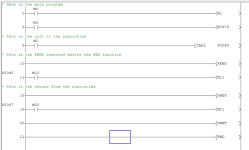
"Eval," as in "STATE_EVAL," means
evaluating what State (Step) the PLC model should be "in" (i.e. what is the value of the STATE variable D200) during each scan cycle; this may mean leaving the state at is current value (e.g. waiting for a timer to expire), or transitioning to the next state (e.g. triggering the limit switch that indicates the cylinders are extended and are holding the garment). The blue
transition conditions above define the transitions from state to state. For a simple machine, the completion of each step's
transition condition causes the STATE register value advance to the next state (0 → 10 → 20 → ... → 70 → 0, etc.).
Spaghetti is the italian word for noodles:
"Spaghetti" in the context of programming is a nickname for "spaghetti code," where a program's logic flow is convoluted and difficult to follow.
"No spaghetti" describes how you want the program to look, because you will spend a lot more time
reading code than you will spend
writing code, and having the program be as clear as possible makes it easier to read. Let's look at your code for a moment:

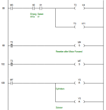
Let's say we were interested in how the Motor Direction is set up to be in reverse. We know that the Motor Direction is controlled by output Y6, and so we find the rung @112, the bottom rung in that image, and that the value of Y6 is SET to 1 on that rung. We look to the left and see the condition(s) that cause the SET instruction to write a value of 1 to Y6, and we see that the only condition is a rising edge of bit M4. So now we search for the rung that assigns the value M4, and we have to follow the blue line, like a tangled noodle or a piece of tangled spaghetti, across two other unrelated rungs (@106 and @102), before we get to the rung @98, and we see that M4 may have a rising edge when the T2 timer expires. And then another piece of tangled spaghetti finally gets us to the rung @86, where we see an unlabelled bit, M3, controlling the T2 timer.
From this example, I hope you now know what I mean by "spaghetti" (or "spaghetti code"). And not to put too fine a point on it, but this example is the reason it took so long for anyone, including yourself, to understand your code well enough to know why the motor was not reversing on the second cycle.
I want you to try an experiment in Rubber Duck Debugging (see
here): please explain to yourself (or your "rubber duck," if you have one
")
), why the M4 bit exists in this program; that is. provide the rationale why you have the T2 expiry bit going though the M4 bit to get to the Y6 output bit. I'll bet you can't even convince yourself of a good reason. Would it not be better to do it much more simply, like this:

where you can see immediately, in
one rung with
no spaghetti, where the Motor Direction is set. I know some programmers will say that that should be two, or even three or four rungs, and that each rung should do one thing, and I don't disagree with that. But certainly those M4 (and M7) intermediate bits are completely unnecessary.
"Refactoring" is taking a program that is hard to read and understand, but works, like yours, and changing the organization, data structures, logic, etc. as needed so that the program behaves exactly the same way it did before, with the same interfaces (inputs and outputs), but is now a better program. Better might mean "more efficient," or "more flexible," or "easier to read and understand and debug."

 , I am not going to do that again.