1794-VHSC Counter Mode / Module Faulting

AD-PLC

Supporting Member
Join Date
Jul 2021
Location
Illinois
Posts
13
Hey Everyone,
After reading a lot on this forum and elsewhere I see not many are fond of the 1794-VHSC module. I can see to a degree as I was running across issues with it as well. I'm using this module to count pulses from a flow meter. I did not know if I would need the module and could possibly get away with just using a digital input. What is nice about the flow meter is that it has a scalable pulse output feature. I'm choosing to do 100:1.
This is a two part question. Does anyone know the correct wiring for this module. I did get it to count on the A input. Though according to the manual the A indicator should be flashing. When I talked it over with a co-worker we ended up putting 0V to the A- terminal and that is when it started flashing. It still counted but we got pulses just rising when there was no flow. It would count past 1000 pulses after target was met. The manual directly says that the A,A_ are 24V inputs. Which I'm assuming is for an encoder. (I have no experience with encoders). The card should need a 0V reference correct?
1711581797636.png

Second part,
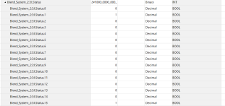
Has anyone had experience with this module faulting? It seemed to work for many days straight then all of a sudden the module (not the 1794-AENTR) started flashing. Went through the manual. Power is Ok, it was not left in PROG mode, no network cable disconnected or faulty. There were status bits set to one. Status.1 and status.15. When the module started flashing it would not allow pulse capture.
There are no active filters for any counter
The rollover is set to 16777215
The mode selected is counter
Signs point to a configuration issue but I do not know what.
1711582405106.png

1769-L30 PLC
This rack has an AENTR, digital input module, digital output module, analog in module and VHSC
 
What kind of flow meter are you using, and what voltage and style of output does it have ?

Ordinary discrete modules generally have a 0V common reference, and you supply +24V to each input. But encoders frequently use differential signaling for noise immunity, so the VHSC was built to accept those. To use a single-ended device with a differential input, as your colleague recommended, you tie the DC Common to the -Signal terminal.

For a single pulse generator, that's typically going to be the flowmeter output wired to +A, and the flowmeter DC common wired to -A.

The diagram on Page 19 of the user manual might be instructive, where it shows a mechanical dry contact connected to the second counter's Z-input. The -Z is connected to module DC Common, and the +Z is connected through that dry contact to the module +24V power. That's an example of combining the module's logic power and the input channel power.

Probably the biggest gripe I have about this module also applies generally across the FLEX line; if you use the same power supply for both the network adapter and the analog/specialty I/O modules, then sometimes the network adapter doesn't recognize the analog/specialty module on powerup. In the late 90's I added a little timing relay to some of these at a sawmill so that the specialty modules would boot up a second before the I/O Adapter did.

I'm a little mystified by the module accumulating pulses while there's no flow, but if the input is flashing then it's probably getting a signal that it considers a pulse. You often need to have an oscilloscope or scopemeter to get to the bottom of signals of that type.

>Counter Mode

If you set up the module in Counter mode, it will do just that: it will count. It doesn't stop counting when it reaches the Preset: it just turns on the Output (if you've set an output threshold) and keeps counting until it gets a Reset pulse or a software Reset command. It rolls over to zero when it reaches the rollover value.

For a flowmeter, you probably want to set the module up in Rate Measurement mode. That causes it to count the pulses on Channel A over a user-defined period of time, then deliver both a pulse count and a pulses/time rate.
 
I'm puzzled by the apparent configuration fault as well. Where exactly did you see Bit 1 and Bit 15 set ?
 
@Ken Roach,
I delayed my response because I wanted to do some background research on some of the terminology you used (single vs diff). I have a much more better understanding of these circuits. It added depth so thank you.
1711633356121.png1711633538307.png

The drawing is how the OEM said it should be connected. The pulse output is an open-collector type (optocoupler based). Meter is a Turbine Inc. I brought 24VDC power to terminal 5. Have the pull up resistor in line (1.5Kohm, Ok'd by OEM). Out of terminal 5 it goes to the A input. 0V is brought to terminal 6.
The circle portion is what is recommended by the OEM without using the loop power to power the meter. I originally did have loop-power connected but toward the end I switched it back to battery operation. It worked but this is where the pulses just ran away. I did have 0V at the A_ at this point as well to see what I got. I brought the 0V from my COM rail in the control panel to the module card.

I also forgot to mention that I was losing pulses as well. The monitor (factory default) would give an "E" status indicating the the pulse output was losing pulses. About 50-60% of the pulses were being lost. I explained to them that with all their defaults and recommended changes we got the error off the flow meter monitor. But even with this error the pulses just ran away when the system was not running. At about 1000 pulse overshoot then it would stop.

See screenshots of status.
It's in the monitor tag section of the controller tags. I went to the vhsc counter module of the system having issues. There is a fault section but nothing had a 1 bit in it. The status section did have active bits. The manual said it is based of WORD. If I read it correctly it gave you issues related to configuration. I though status.14 was active as well but this is what was saved before going offline.
 

Attachments

  • status1of2.png
    status1of2.png
    2.6 KB · Views: 5
  • status2of2.png
    status2of2.png
    42.6 KB · Views: 7

Similar Topics

Hello all. I have an issue I have not been able to find an answer to online. I have a 1794-VHSC connected to a Contrologix PLC and a Sick...
Replies
5
Views
2,417
So I have a customer that wants to replace an outdated PLS (Programmable Limit Switch). The current system uses a resolver and 2 outputs in a...
Replies
2
Views
2,301
Hi all. This would be my first post on this forum, but i have so say i have been following it for quite some time and it has provided me with alot...
Replies
4
Views
3,205
  • Poll
I have a 1794-VHSC card (encoder counter card) connected to a 1794-ADN scanner module. When I try to add the module in the right slot in the ADN...
Replies
7
Views
5,834
1794-VHSC Flex IO module. I have a encoder with only 1 channel. So it has 3 wires: 24vdc, vdc common, Channel A. I hook it up and configure the...
Replies
18
Views
8,420
Back
Top Bottom