Mitsubishi Q series: Averaging value before displaying on HMI

Mas01

Member
Join Date
Oct 2020
Location
Leicester, England
Posts
1,105
The PLC code calculates oil flow rate and outputs it on D420. It is represented on the HMI as a vertical bar. Problem is that the operator says the value is too jittery to read as the value is constantly changing (I agree - it is doing several updates every second). To make it more readable, it was suggested that the displayed value be the average of the previous 10 values of D420.
Is this a good idea to make the value readable?
If so, I'm not sure how to do this.
I would need a counter (T10, say) that goes to 0 to 9 then resets.
I would need an accumulator i.e
---[+ D420 D422]---
Then a division
----[/ D422 k10 D424]----
Then display D424 on the HMI.

I'm not sure how to implement this.
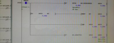
IMG_20220325_114211.jpg
 
No experience with Mitsubishi.
But you can use a fifo with 10 values, a new value will be entered into the queue due to a timer, so if your timer trigger every 6 seconds for instance, you will have a new average value every 6 seconds.
You can set up you timer as you desire.
 
Well here is a dirty way of doing it, there is a word shift but not sure that the processor you have will support it (I will look), basically, every second (SM412) we do a block transfer from D420 to D421 10 registers this effectively shifts the values by one register so D421 to D430 are moved by one each second, then the registers are added up & the total in D431 is divided by 10 & stored in D432 so gives a running average in D432, just check all those registers are free or select another 12 registers.
There is another way using indirect addressing but get it wrong it will shut the PLC down I will post it when I code it, with an explanation
 
No experience with Mitsubishi.
But you can use a fifo with 10 values, a new value will be entered into the queue due to a timer, so if your timer trigger every 6 seconds for instance, you will have a new average value every 6 seconds.
You can set up you timer as you desire.
+1

1) Moving average, reduces jitter by 1/N

Start with

  • an array, LASTn, of N floating point values, all initialized to 0.0,
    • I don't know how arrays, array indexing, and floating point values are implemented in Dnnn registers; that is left as an exercise
  • an integer index, INDEX, into the array, initialized to 0,
  • a floating point value, AVERAGE, initialized to 0.0.
  • a timer arranged to generate a one-shot (a bit that is 1 for one scan) at a regular sample time
  • the tag you want to average, i.e. D420.
Every time the one-shot bit is 1,

  • Subtract the current value of LASTn[INDEX] from AVERAGE, and put the result into AVERAGE
  • Divide D420 by N, and replace the current value in LASTn[INDEX] with the result of that division
  • Add the current value of LASTn[INDEX] to AVERAGE, and put the result into AVERAGE
  • Add 1 to INDEX and put the sum into INDEX
  • If INDEX is greater than N-1, put a 0 into INDEX OR
  • Or, if N is an integral power of 2, then do [WAND N N-1 N], where WAND does a bit-wise AND of integers
  • Caveat
    • There is a small error from the summing, that may accumulate over time, losing about one significant decimal digits for every power of 8 in N (1 digit for N=8 or 1 part in a few million, two for N=64).


2) Exponentially-weighted moving average, reduces jitter by 1.0-K

Another approach, without the array and indexing, would be to take the last AVERAGE, multiply it by a number K between 0 and 1, and multiply D420 by 1.0-K, and sum those products back into AVERAGE. K should probably be in the 0.9+ range, but that depends how often it is run.
 
Last edited:
Well here is a dirty way of doing it, there is a word shift but not sure that the processor you have will support it (I will look), basically, every second (SM412) we do a block transfer from D420 to D421 10 registers this effectively shifts the values by one register so D421 to D430 are moved by one each second, then the registers are added up & the total in D431 is divided by 10 & stored in D432 so gives a running average in D432, just check all those registers are free or select another 12 registers.
There is another way using indirect addressing but get it wrong it will shut the PLC down I will post it when I code it, with an explanation

+1

http://www.atronika.com/Mitsubishi/PLC/MITSUBISHI_QL-Simple-Mode-Programming-Manual-Common-Instructions.pdf#M22.9.93341.TitleSub.7515.Calculation.of.averages.for.16bit.or.32bit.data

...
http://www.atronika.com/Mitsubishi/...lculation.of.averages.for.16bit.or.32bit.data
 
Argh.. I forgot it was a float let me look if it can be done in float I don't think the shift function or the sum functions have float type will get back to you
 
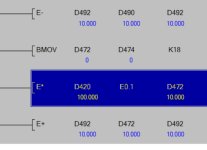
By way of experiment, I also tried using D45 instead of D420. D45 is the "raw" analogue integer input into the PLC. I still get some odd values. I did make sure that D472 to D483 were all unused registers.

IMG_20220325_154156.jpg
 
Last edited:
I also forgot it's floating point so this is how to do it.
It means you need at least 24 registers spare I have shown them as D420 to D446 but there is no reason why you could not use another area i.e. perhaps move D420 to say D700 then use D700 to D724
EDIT as there is no SUM or Average functions for floats I have had to do it the hard way, note the shift function is the same but the two constants "K" are 22 instead of 11 & 2 instead of 1 the reason is because a float requires two registers as it moves the data directly it does not need to know if it is a float, only the addition & subtraction functions have to be floats.
 
Last edited:
The BMOVP should not care about float or int, we need only double the length of the move:

SM412
--] [-+--[E-P D492 D490 D492]-- ### Subtract oldest scaled float [d490:d491] from average float [d492:d493]
|
+--[BMOVP D472 D474 K18 ]-- ### Shift eighteen newest words (nine scaled floats) [d472:d489] to eighteen oldest words (nine scaled floats)[d474:d491]
|
+--[E/P D420 E10 D472]-- ### Scale current float measurement, save as newest scaled float [d472:d473]
|
+--[E+P D492 D472 D492]-- ### Added newest scaled [d472:d473] float to average [d492:d493]


Mitsi BMOVP claims to handle overlapped Source and Destination, but the shift could be done in the opposite direction if it does not.
 
Last edited:
Yes but allowed a couple spare so that rather than overwriting directly just leave them separate so you can see the intermediate
Block move is what I showed first time but even though the shift is word it also allows double shift.
 

Similar Topics

In this sample programming, what does U4 mean? Any assistance would be greatly appreciated.
Replies
8
Views
230
Hi, I have a project with a R04CPU, RD77GF16 and a RJ71PN92 modules. The cell is given to me to change the program since the previous integrator...
Replies
9
Views
264
Hi One of the PLC's that I maintain/update is a Mitsubishi Q-Series, probably installed about 10 years ago. At the moment, ALL the wires from...
Replies
13
Views
1,161
Hello All, I have an existing Mitsubishi L06CPU-06 PLC, and I am going to add a new serial communication card, LJ71C24, for modbus communication...
Replies
0
Views
469
I need to send a signal to our PLC (Mitsubishi Q series) which is TRUE when there's current flowing and FALSE otherwise. The thing is, the cable...
Replies
31
Views
10,113
Back
Top Bottom