Friday's talks about control

Pandiani

Lifetime Supporting Member
Join Date
Apr 2005
Location
Tz
Posts
718
Hello guys,

lately, I've been struggling with some of control loops in my plant. I've tuned loops as many of us would do, by trial and error. I couldn't get meaningful information by bumping process with step CO change (as suggested in the article on controlguru.com). I was able to find satisfactory response and I'm fine with that. While trying to improve control performance I 've read some of the articles posted on controlguru.com again. Most interesting I find is the part about anti windup integral logic that was described in the article(http://www.controlguru.com/2008/021008.html).
Now, I saw how some people implements this windup protection, but I have a hard time to understand what is described in "solution 1":
"With our controller properly initialized, the approach is to flip the algorithm around and back-calculate a value for the integral sum of error that will provide a desired controller output value (COdesired)"

inegral(error) = (COdesired-CObias-Kc*error)/Ki
What does this really means? Is it like sign of integral action is reversed?

Also one more thing. In the second article about concrete implementations of PI controllers that uses multiplicative form (
position PI form used in controlguru), I read something like this: "Integrator is provided with corrective element which reduces integral reset time in case of large control deviation (error value = SP-PV)". In this position PI form it means that overall integral component of PI controller will be increased since reset time is reduced. So this doesn't fit the story about windup prevention.

I'm a little bit confused about this and like to make this clear with your help.

Thanks
 
Last edited:
I might have misunderstood what you are after.
For a standard control loop (so we are on the same page), you have setpoint (operator input), process value (transmitters) and control value (valve). We assume steady state where the SP and PV are equal at 40% and the CV at 25%.
Anti-windup is so that if you change the setpoint to 80%, the CV will gradually open up (depending upon your control tuning depends upon the response). In this example, the CV is at 100% and the PV is only at 60% (increasing at 2% per second). Your Porportional term is decreasing as the error (SP-PV) is decreasing, while your integral term is still increasing (area between the SP and PV lines from where they digresses. This means that the control loop is 'trying' to open the CV more than 100%.
After 2 mins, the SP is still 80%, PV is 75%, CV is 100%. Now you change the SP back to 40%. Your Proportional term is now -ve, but your integral is still VERY positive (as you still have that 2 mins of 'area between the SP and PV', therefore CV will still be 100%. The integral term is decreasing as the '-ve' area between the SP and PV is increasing' (if my explaination is ****, draw what I'm writing, it might make more sense). Eventually the proportional term (which is fixed since the SP and PV are currently stationary) will be less more than the integral term, therefor teh CV will start to decrease. This will continue to happen as the integral term will also decrease.

Anti-windup stops the integral term from accumulating when the CV is at its limit (100% for this example). Therefore when the SP was reduced to 40%, the CV would react instantly as the integral term would intially be zero.

I hope I have helped instead of hindered. Its going to be one of those light bulb thingies.
 
Do it the way I do it. You have seen plenty of my examples.

You are capable of rolling your own SCL PID using the techniques I use. You can see that I can drive the control output into saturation and come out of saturation without any problems.

Code:
[font=Verdana][size=2]inegral(error) = (COdesired-CObias-Kc*error)/Ki
   What does this really means? Is it like sign of integral action is reversed?
This is what I do but I don't keep track of the sum of errors. It is much harder to implement anti windup that way. Instead I keep track of the integrators contribution to the control output. Again, you have seen examples of how I limit the integrator contribution. Let me know if you need a simple to implement example.


[/size][/font]
 
Guys, thank you for the replies. When I'm making my own code, I usually do the same as Peter, but in this case this is absolutely impossible because I'm using blocks that are already made in my DCS system. So I don't have opportunity to experiment.
creativepaper , I know what integrator windup is.

My second question about ""Integrator is provided with corrective element which reduces integral reset time in case of large control deviation (error value = SP-PV)" is related to the PI step controller I have to use in my DCS system. Block diagram is in the attachment.
I always use multiplicative algorithm Kc*(error + integral(error)). In the documentation nothing is written about windup prevention but I do have inputs for changing the sign of the integral sum. Obviously I need to make I want with something I have. Since downtime is very costly I don't want to try somethnig until I'm sure I'm on the right track,

Now, I don't understand that part in that says in case of large control deviation, corrective factor will reduce integral - reset time. This way it will increase the integral component, and this will not help fighting integrator windup problem.

On the other hand I saw implementations (level control) where integrator is switching off. Remember my control loop http://plctalk.net/qanda/attachment.php?attachmentid=7958&d=1206897666)
http://plctalk.net/qanda/attachment.php?attachmentid=7958&d=1206897666)
example

Here because of the shape of condenser when level is above certain point and falling integrator is temporary turned off (reset time from 60 to 600).

 
Guys, I manage to get complete article about step controller. Maybe some of you will remember a long time ago I asked about so called step controller. Basically it is a controller which has three position switch (realized with relays and hysteresis). First position "R" (clockwise direction), "L" (counterclockwise direction) and OFF state. I moves final control element in steps by generating pulses that will produce moving in one or the other direction.
I gave you a part of my documentation about PI controller. It is step controller. I have found out that this kind of controller is turning off integrator (I part) during pulse duration in either "R" or "L" direction. If control deviation (error signal) that enters this controller is large, then pulses will last longer and there will be more of them. Because of that Integrator (I1 ) in the first attached file will work for a smaller amount of time and because of that integral component will be weak.
In order to prevent that, a correction block reduces reset time in case of large inputs just to compensate, i.e. to make integral component stronger because integrator will work less.
That's all. It has nothing to do with integrator windup prevention.

So, I guess that engineer needs to handle integrator windup problem by adjusting binary inputs ISPO (integrator sign positive) or ISNE (integrator sign negative).
I saw this can be handy in case of loose mechanical linkage in the control valve and valve cannot be taken to repair because it would cause downtime of the plant.
This can be seen as sudden increase or decrease of flow through valve making harder to maintain level control loops. Sudden change in level would produce large error which could cause integrator windup.
Other approach would be the following. If you know that according to technology some level or whatever needs to be maintain on the value between PV1 and PV2. Than one can define the following logic:
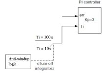
if current process value is SP + threshold and continue rising or current PV is SP - threshold and decreasing, then switch integral time to say 10*Ti (that is going to weak integral component) and make windup less probable. Do you agree with this?
This can be done when one need to use PI block from the library, and there is no way to go to inner structure or write code. I would always use complete block from the library instead of using my own implementation. Just trying to find way to prevent problems in easiest way.

These are certainly interesting things.
 
Last edited:
Case study Siemens STEP 7 PID FB41

Kludge!?!, hmm, maybe...
Whenever I make simulations by writing Scilab or Matlab scripts I use your way Peter, of using saturation block on integral component.
Now what about structures when you cannot penetrate and play with inner structure.
Do you remember this thread?
There I came to true conclusion that Siemens standard PID block FB41 does implements anti windup, by looking on its parameters.
Now I feel the need to correct this and to explain.
Please look at the attached picture of Siemens FB41 PID:
http://www.plctalk.net/qanda/uploads/PID1_FB41.JPG
Note that there is a saturation block on manipulated variable (CO - controller output). Engineer can define upper and lower limit of this saturation block. When CO reaches limits defined by parameters LMN_HLM or LMN_LLM, CO will saturate and integrator will stop integrate (I tested this behavior on PI controller). If you change SP in opposite direction, integrator will start integrate in the other way immediately and everything is OK.
This can be considered as one way of implementing anti windup.

Other approach is to use binary input parameter: INT_HOLD. If this binary input is set to true, integrator will start integrating keeping current value at its output.
This is second way of integrating anti windup logic. I guess it's up to engineer to decide what works better for him.
I would personally try to hold integral component first and see how this would work.
 
Last edited:
Case study Siemens DCS T2000, PI FB90 step controller

Now, somewhat different story is when dealing with the function block that is not so flexible.
For example, in the earlier attached block diagram (which can be misleading by just observing structure...) there is PI step controller. Step controller means that output is a series of pulses of different duration depending of the magnitude of error (control deviation). Pulse generator is basically a three position switch that has three states: ON in "Right" direction, ON in "Left" direction and OFF. In this particular case, there is also a saturation block at the controller output. However, meaning is different. If calculated CO reaches high limit value, a permanent pulse is output to the actuator (for instance in "R" direction). If CO reaches low limit value, a permanent pulse is generated to opposite direction. This logic makes it clear that this block doesn't have any anti windup prevention option like S7 FB41. Anti windup must be implemented otherwise.
One way is to think a clever logic and use ISPO and ISNE binary inputs. These will not stop integrator but they can change the sign. Also if both inputs are set to zero, then controller is acting as P-only but it is not specified if integrator is stopped at current value or not. Also there is IAUS that can turn off the integral component, but unfortunately there is also a lack of description what happens to integral component (current value) when IAUS input is set to false. This behavior must be determined by actual testing on running plant which is very unwise (there are no simulators or separate components outputs).

So in this case, I would go with analog switch that would switch integral time from (example) 10s to 100s to weak integral component if some process conditions that could cause windup occur.

I hope I've done my homework for the weekend. I hope someone will find this useful.

Regards,
Asim V.

Antiwindup.jpg
 
Last edited:
Kludge!?!, hmm, maybe...
If it doesn't have a transfer function stamped on it is a kludge. It looks like the mechanical designer just threw it together and let the control guy just made it work in some arbitrary way. I hope that when you are running things you are more demanding and have higher standards for what passes as control documentation.

There I came to true conclusion that Siemens standard PID block FB41 does implements anti windup, by looking on its parameters.
Do you have access to the sum of errors or the integrators contribution to the control output? Then you can start limiting this term. It must be a a FB somewhere.

Now I feel the need to correct this and to explain.
Please look at the attached picture of Siemens FB41 PID:
http://www.plctalk.net/qanda/uploads/PID1_FB41.JPG
Note that there is a saturation block on manipulated variable (CO - controller output). Engineer can define upper and lower limit of this saturation block.
Is that the total control output or just the integrator's term?

When CO reaches limits defined by parameters LMN_HLM or LMN_LLM, CO will saturate and integrator will stop integrate (I tested this behavior on PI controller).
You must be doing some 'homework' then.
If you change SP in opposite direction, integrator will start integrate in the other way immediately and everything is OK.
[/quote]
Yes, but what happens when the control output saturates when the integrator output is 50% and the proportional output is 50% and the integrator output is frozen at 50% yet the proportional output continues to increase to 110%?

This can be considered as one way of implementing anti windup.
Other approach is to use binary input parameter: INT_HOLD. If this binary input is set to true, integrator will start
You mean stop don't you?

integrating keeping current value at its output.
This is second way of integrating anti windup logic. I guess it's up to engineer to decide what works better for him.
I would personally try to hold integral component first and see how this would work.
Would it pass my test from above?

There is only one problem with my method of anti windup. When the error reverses it takes 5 integrator time constants for the integrator to reach it new correct value. If the integrator gain is not tuned or calculated correctly, the integrator time constant is too long or slow, then the PV will overshoot.

Proper tuning is also part of making anti windup work. There was a thread about this on the sci.engr.control user group.
http://tinyurl.com/5oggag
Notice that most people were speaking without knowing what they were talking about.
 
Last edited:
Peter Nachtwey said:
Do you have access to the sum of errors or the integrators contribution to the control output? Then you can start limiting this term. It must be a a FB somewhere.
Yes, just look at the block diagram. There is output parameter LMN_I.

Peter Nachtwey said:
Is that the total control output or just the integrator's term?
Saturation block is only for total control output.
Peter Nachtwey said:
You must be doing some 'homework' then.
As you can see...

Peter Nachtwey said:
Yes, but what happens when the control output saturates when the integrator output is 50% and the proportional output is 50% and the integrator output is frozen at 50% yet the proportional output continues to increase to 110%?

For example if error is 1, gain = 1 and Ti = 10s. P-only component is 1.0, while integrator keeps working and increasing CO. When it hits high limit, CO stops and P-only is still gain*error = 1. If error decreases to 0.5 (for example SP is changed), LMN_P experience step change to gain*error = 0.5, and integrator starts decreasing from value that was remembered while in stop.

Peter Nachtwey said:
You mean stop don't you?
Homer Simpson would say: "D'OH"

Peter Nachtwey said:
Proper tuning is also part of making anti windup work. There was a thread about this on the sci.engr.control user group.
http://tinyurl.com/5oggag
Notice that most people were speaking without knowing what they were talking about.
I agree, this is why I don't like to post on sci.engr.control.
There are enough people who know what they're talking about on this forum.
Hopefully Gabe's controltheorypro.com will become major resource of this kind of materials in the future (except this site, of course...)
 
Last edited:

Similar Topics

Retirement Milestone It’s been an amazing 42 year trip. I have had great fun, seen amazing technologies, met good friends, learned something new...
Replies
36
Views
7,401
I usually can find what answers I need in the archives but thought I'm tired, it's been one of those weeks and I could not find the answer last...
Replies
1
Views
1,924
What is your ‘Strategy’ to these 4 ‘Insights’? This is taken from a slide in a sales presentation done recently, my edits are in ( brackets )...
Replies
1
Views
2,023
For you guys trained by the US Military and Drone aficionados. One of the first Carrier TO&L of a Drone...
Replies
20
Views
5,588
AirAware Credits: http://xkcd.com/1207/
Replies
1
Views
1,719
Back
Top Bottom